xPlora: Barrier Gate
Introduction
When you go to the mall or a parking lot, you might see a long arm that goes up and down to let cars in and out. This is called a barrier gate.
Barrier gates help control which cars are allowed to pass …. like when making a payment, going through security checks, or keeping track of cars coming and going. When a car is allowed in, the gate lifts up. After the car goes through, it comes back down.
It’s a smart and simple way to keep traffic safe and organized.
You’ll find barrier gates at malls, schools, toll booths, and office buildings. They help manage traffic and make sure only the right cars get in.
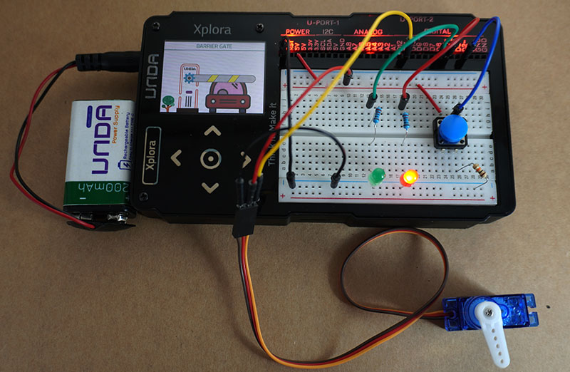
Barrier gates use a motor to move the arm up and down. In this project, you’ll build your own mini barrier gate using a small servo motor that turns smoothly to open or close the gate.
When you press a button, the motor turns one way. Press it again, and the motor turns the other way.
Let’s get started and build your very own barrier gate!
Build the project
In this section we will explore how to use UNDA.Xplora to build the Barrier Gate Project.
Components
To build the project you will need:
| Component | Description |
|---|---|
| 1 x Servo Motor | 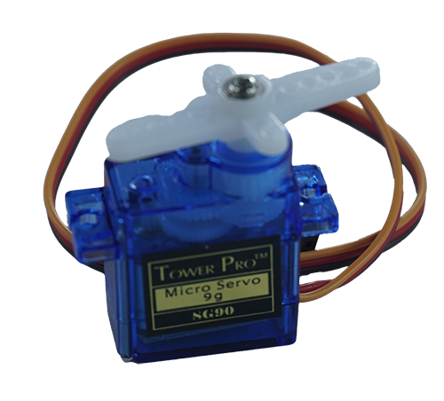 |
| 1 x pushbutton | 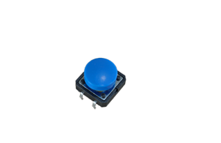 |
| 2 x LED(Red and Green) | 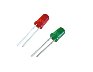 |
| 2 x resistor (220 Ohm) | 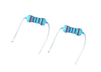 |
| 1 x resistor (10Kilo-Ohm) | 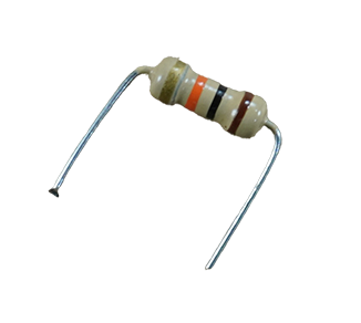 |
| 7 x jumper wire | 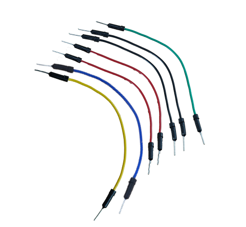 |
| 2 x breadboarding jumper wire | 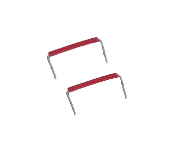 |
| 1 x battery connector | 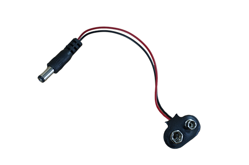 |
| 1 x battery | 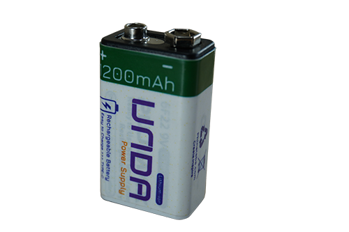 |
| 1 x Unda Xplora | 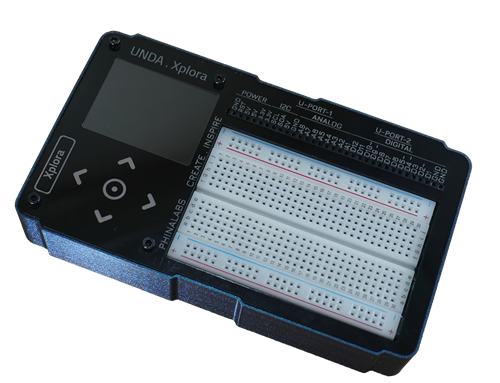 |
Step 1
Connecting the Pushbutton on the breadboard
- Step
- Build
-
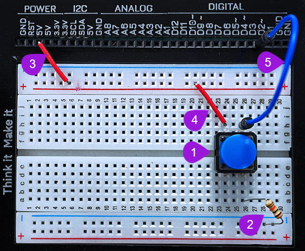
Connecting the pushbutton: Take one pushbutton and connect it's two top pins into pin d26 and pin d24. Insert the two bottom pins into pin g26 and pin g24. It is worth noting that as long as the top pins are inserted correctly, the bottom pins will easily insert into their respective pins.
-
Connecting a 10 Kilo-ohm resistor: Take one 10 Kilo-ohm resistor and connect one of its' end into any pin of the bottom breadboard rail. Insert the other end into breadboard pin a26 next to one of the bottom pins of pushbutton.
-
Connecting power to the breadboard: Using a breadboarding jumper wire, connect from any 5V pin of the UNDA.Xplora to any breadboard pin of the top positive breadboard rail as shown above. Remember that the positive rail is marked with plus (+) sign and marked by red solid line.
-
Connecting the button to power: Take a second breadboarding jumper wire and insert one of the ends of the breadboarding wire into any breadboard pin of the top positive breadboard rail. Insert the second end of the breadboarding wire into breadboard pin h24 next to the second top pin of the pushbutton.
-
Connecting the button to digital pin D2: Using a jumper wire(pick any color of your choice), connect from digital pin D2 to one side of the pushbutton at breadboard pin h26 of the breadoard.
Step 2
Connecting the Red LED on the breadboard
- Step
- Build
-
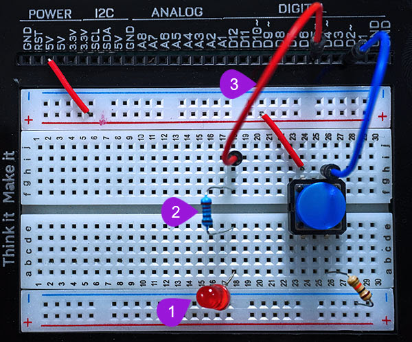
Inserting the Red LED: Pick a Red LED from the Tinker Components Casing. LEDs have two legs, that is positive (the longer leg) and negative leg (the shorter leg). Insert the negative leg of the LED into any pin on the bottom negative breadboard rail. Insert the positive leg of th LED into breadboard pin a18.
-
Inserting the resistor: Take one 220 ohm resistor and place it on the breadboard, with one of its leg next to the positive leg of the Red LED at pin e18 and the other leg placed at pin f18 of the breadboard.
-
Connecting the LED to digital pin D5: Pick a jumper wire of any color of your choice and connect it from digital pin D5 of the kit to one side of the resistor at breadboard pin i18 of the breadboard.
Step 3
Connecting the Green LED on the breadboard
- Step
- Build
-
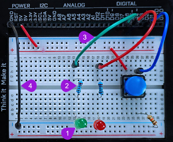
Inserting the Green LED: Pick a Green LED from the Tinker Components Casing. LEDs have two legs, that is positive (the longer leg) and negative leg (the shorter leg). Insert the negative leg of the LED into any pin on the bottom negative breadboard rail. Insert the positive leg of th LED into breadboard pin a13.
-
Inserting the resistor: Take one 220 ohm resistor and place it on the breadboard, with one of its leg next to the positive leg of the Red LED at pin e13 and the other leg placed at pin f13 of the breadboard.
-
Connecting the LED to digital pin D5: Pick a jumper wire of any color of your choice and connect it from digital pin D5 of the kit to one side of the resistor at breadboard pin i13 of the breadboard.
-
Connecting the GND Pin: Take another jumper wire and insert one end of the jumper wire into any GND Pin of the kit. Insert the second end of the jumper wire into any pin of the bottom negative breadboard rail.
Step 4
Preparing the Servo Motor
Important Tip: Ask for help from an adult to fix the servo arm on the servo motor. To attach the arm:
-
Take the servo arm ( the one with a single arm) and fit it into the servo motor's shaft.
-
Insert a screw through the hole in the servo arm and then use a screw driver to tighten the screw and secure the arm firmly on the motor's shaft.
You can watch the video step below.
The servo motor also has
- Step
- Build
-
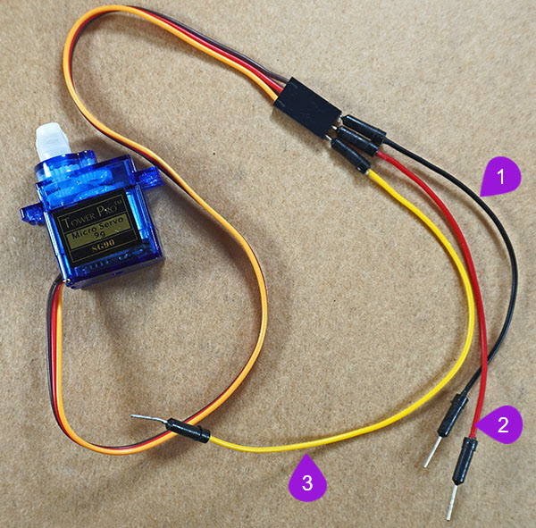
Connecting to the negative pin of the motor: The servo has a three-pin female connector that is connected to the pins of the motor via electrical wires. The brown wire connects to the negative pin while the red wire connects to the positive pin of the servo motor. The yellow wire connects to the signal pin of the motor. Take a black jumper wire and insert one end of the wire into the first female connector of the motor; the connector connected to the brown wire.
-
Connecting to the positive pin of the motor: Take a red jumper wire and insert one end of the jumper wire into the second female connector of the servo motor; the connector connected to the red wire.
-
Connecting to the signal pin of the motor: Take a yellow jumper wire and insert one end of the jumper wire into the third female connector of the servo motor; the connector connected to the yellow wire.
Step 5
Conencting the Servo Motor on the breadboard
- Step
- Build
-
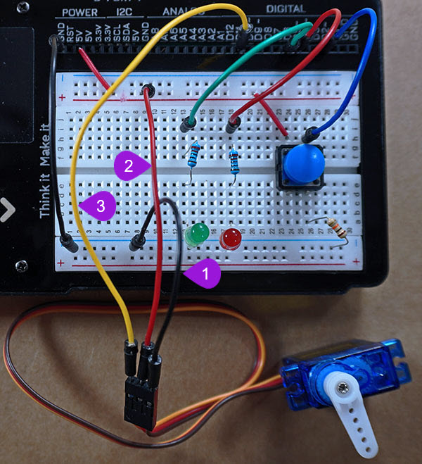
Connecting the motor to GND: Take the other end of the black jumper wire and then insert it into any breadboard pin on the bottom negative breadboard rail.
-
Connecting the motor to Power: Take the second end of the red jumper wire and insert it into any breadboard pin on the top positive breadboard rail.
-
Connecting the motor to digital pin D11: Take the second end of the yellow jumper wire and insert it into digital pin D11 of your UNDA. Xplora.
Run the Project
Once you are done with building the project, connect the battery to the battery connector and then plug it to the power port of your Unda Xplora to power it on.
Follow the steps below to load up the Barrier Gate Project.
Open Project
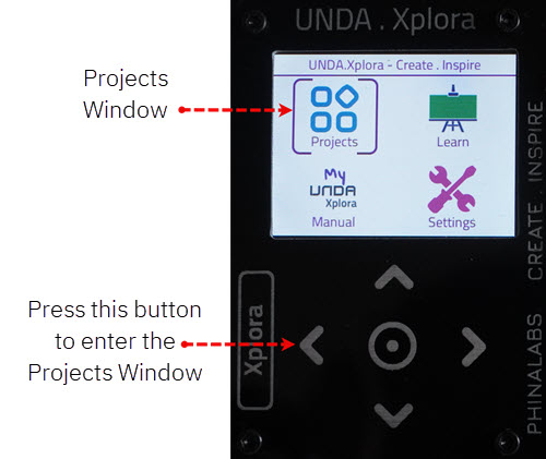
From the main window open the projects